|
Why you need a GROUND ZERO:
Before you can set up and use GROUND ZERO to eliminate your ground loop problems and improve your system's performance with a lower noise floor, it is helpful to have some basic understanding of how GROUND ZERO works.
Ground loop problems generally begin when there is a difference in the ground potentials of the various components in a system. The ground potential of one component may be higher or lower than that of another connected component and the component's ground path to earth ground, or ground impedance, may be higher or lower than that of the other connected component. The result of a ground loop is audible hum, usually 60 cycle, that sounds like a low bass rumble. The noise can be extremely objectionable if it can be heard over the music or during quiet passages. Since the noise is low frequency, it also robs your system of available dynamic power because the amps are wasting their resources by amplifying this audible signal. An audible ground loop robs system power.
These unbalanced components share a common ground bond between them via the shields of their interconnect cables, or via the ground wire of their AC power cords. The ground bond created by the interconnect shields is problematic because of the small gauge of the wires, dirty contact surfaces, and the sometimes low mechanical integrity of the outer grounding ring of cheaper RCA plugs. If your RCA plugs have a lose fit, you have a potential grounding problem.
The ground bond via the AC power cords can be problematic because the cords may be different gauges, have different contact mechanical integrity at the outlet, and have different distances to travel back to earth ground. All these variables can create differences in the ground impedance of each component and opens the door for ground loops and system noise.
How GROUND ZERO works:
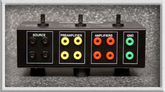
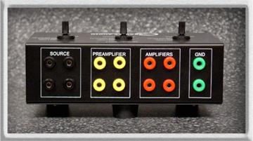
This is where GROUND ZERO does it's work. It functions totally in the ground circuit, so there's no interference with the music signal path. GROUND ZERO first bonds all the components together in a central star location with identical wires & terminations. The wires are all of the same large gauge and ultra-pure OFC flexible copper for identical low-impedance ground paths. Then all the terminations are gold plated and soldered to the copper wires for low impedance and long life integrity. The chassis banana jacks are one-piece construction and internal wires are also heavy gauge & soldered. The toggle impedance balancing switches are the most expensive parts in GROUND ZERO . These switches are ultra-low impedance, less than 5 milliohms, and have silver contacts rated at an impressive 32 amps per switch for long life integrity. So, GROUND ZERO presents a super high integrity, and uniform ultra-low impedance matching system for your components.
Any 2 components connected to the same color banana jacks will always have their GROUND ZERO cables at the same impedance, regardless of the position of any of the toggle switches. So, components connected to the same color jacks are bonded to each other at the jack itself at the lowest possible impedance, and this will not change with changes in switch positions.
Components that are connected to different colored jacks have their GROUND ZERO cables isolated by the corresponding toggle switches. This feature allows the user to match and balance the different ground impedances of each section to each other section. Each toggle switch has 3 positions it can be set to. High, Low, or Medium Impedance. These settings determine the ground impedance bond between the 3 sections. With 3 sections, 3 switch positions, and the possibility to plug components into different sections; there are a minimum of 27 different impedance matching settings. Because of the basic design of GROUND ZERO , many different settings will actually yield the same noise floor readings on a decibel meter. But, one or more different settings will give the lowest audible & measurable noise floor. So, relax, there's not 26 wrong settings and only 1 needle in the haystack. Depending on your system, you will probably find that you will get 3 to 5 different results. A result is a difference in the audible or measurable noise.
How to easily install GROUND ZERO in your system:
You are now ready to install GROUND ZERO . All you need is a screwdriver. Make a mental note of your system's noise floor before installation. Be sure to start with your entire system OFF and all components turned OFF. The GROUND ZERO chassis can be located anywhere. Each supplied ground cable has a high quality banana plug on the end that plugs into GROUND ZERO . The other end of the cable has a stepped spade. The step allows this spade to connect to a variety of different sizes of screws and terminals. The spade end connects to your components. It's very important that the spade is only connected to the component's chassis or terminals that are clearly marked "GND" or "GROUND" or are known to be grounded terminals. Never connect any GROUND ZERO cables to positive speaker binding posts, speaker binding posts, any posts marked with red stripes, or any other point that may not be a ground point. If you are not certain of your connecting points, you must consult the factory or other qualified technician before connecting the cables to your components. To avoid getting shocked by components that are faulty, do not handle more than one cable at a time and wear rubber or leather gloves. This safety procedure is necessary because your ground loop may be caused by voltage present on the chassis of faulty or improperly grounded components. This possibly present voltage is why "cheater plugs" are so potentially dangerous.
|
|

